



3D Scan Not Capturing Data? How to Fix 3D Scanning Errors
If you work as a QC engineer, a reverse engineering specialist, or run a metrology lab on a factory floor, you’ve likely run into this scenario: you place a polished metal part, a clear plastic housing, or a black rubber component on your 3D scanner — and what comes back is a broken, incomplete point cloud, or worse, a blank screen with no data at all.
This isn’t a hardware failure, and it isn’t operator error. The problem comes down to basic physics — how light behaves when it hits certain surfaces. This article breaks down the technical reasons behind the failure and gives you practical ways to fix 3D scanning errors, ready to apply on the factory floor.
Why this is a real headache for B2B operations
For reverse engineering shops, QC teams, and mold/tooling manufacturers, 3D scanning isn’t a nice-to-have — it’s the raw input that drives every downstream production step. When your scan data comes back flawed:
- CAD models get reconstructed with dimensional errors, leading to machining inaccuracies.
- Projects fall behind schedule because parts need to be rescanned multiple times.
- Costs go up from surface prep, workarounds, or renting specialized equipment.
- In quality inspection, scan errors can let defective parts slip through the checks meant to catch them.
Understanding the root cause — and knowing how to fix 3D scanning errors before they derail a project — can save real time and budget.
How 3D scanners actually work — and why light is everything
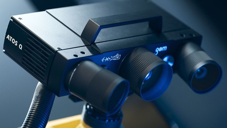
Most modern 3D scanners (structured light or laser triangulation systems) follow the same basic process:
- The scanner projects a pattern of light — a stripe, a grid, or a laser line — onto the object’s surface.
- A camera captures how that light diffusely reflects off the surface.
- Software calculates the distortion in that reflected pattern to reconstruct the 3D coordinates of each point.
This entire process depends on one condition: light needs to scatter evenly and bounce back toward the sensor. Any material that breaks this condition leaves the scanner effectively blind — unable to capture accurate data.
Why shiny (reflective) objects are hard to 3D scan
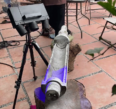
Polished surfaces — stainless steel, chrome, automotive paint, glossy injection-molded plastic — produce specular reflection instead of diffuse reflection. Light hitting these surfaces bounces off at a single sharp angle instead of scattering in multiple directions for the camera to pick up.
The result:
- The camera only picks up bright “hotspots” at a few positions, with dark, data-less gaps everywhere else.
- Software often misreads these reflective flare points as actual surface geometry, introducing errors.
- Noisy, distorted data around edges and curved regions.
Why transparent objects are hard to 3D scan

With glass, clear plastics (acrylic, polycarbonate, PET), or transparent biomedical samples, the problem runs even deeper: light doesn’t reflect off the surface at all — it passes through, refracts, and reflects off internal layers or the back surface instead.
The result:
- The scanner “sees through” the object, capturing both internal and external surfaces and creating overlapping, conflicting data.
- Point positions are calculated incorrectly because the light path has been bent by refraction.
- In many cases, the scanner receives no usable return signal at all.
Why dark or black objects are hard to 3D scan
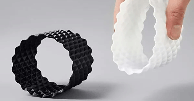
Unlike shiny surfaces, dark objects — especially matte black — absorb most of the incoming light instead of reflecting it back. This is why black rubber, dark plastics, and dark composite materials are consistently one of the toughest challenges in industrial 3D scanning.
The result:
- The reflected light intensity reaching the sensor is too weak to calculate accurate coordinates.
- With laser scanners, the signal can be lost entirely on solid black surfaces.
- Surface detail resolution drops noticeably compared to lighter, matte materials.
5 ways to fix 3D scanning errors on shiny, transparent, and dark objects
1. Use anti-glare scanning spray
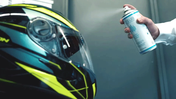
This is the most common and effective industrial fix. The spray leaves a thin, temporary matte coating on the surface, allowing light to scatter diffusely instead of reflecting specularly or passing through. The coating evaporates or wipes off easily afterward without damaging the part.
2. Switch to the right light source and scanner type
- For shiny objects: use a scanner with a polarizing filter to reduce specular glare.
- For transparent objects: consider CT scanning if you need internal geometry, or a blue-laser scanner, which is generally less sensitive to ambient light interference than red laser systems.
- For dark objects: choose a scanner with higher projection intensity or a sensor with a wider dynamic range.
3. Control ambient lighting
Dim overhead lights, avoid direct sunlight, and use a neutral or dark backdrop to cut down on cross-reflections — this matters most when scanning shiny or transparent parts.
4. Increase scan angles and passes
For reflective or geometrically complex parts, capturing more angles gives the software more overlapping data to fill in gaps and align (register) the scans more accurately.
5. Clean up the data in post-processing
For scans that still come back incomplete, software like Geomagic, Artec Studio, or SolidWorks Scan-to-3D includes hole-filling, smoothing, and noise-reduction tools to finish the model properly.
When should you hire a professional 3D scanning service?
If your part falls into the difficult category — highly polished metal, optical glass, engineering-grade black rubber — and the project demands high accuracy (tolerances under 0.05mm) for production or inspection purposes, investing in specialized scanning equipment in-house may not be the most cost-effective route. Between equipment cost and the training required to run it correctly for each material type, the numbers often don’t add up for occasional scanning needs.
This is where outsourcing to a 3D scanning provider experienced with difficult materials becomes the more efficient option. With dedicated structured-light and blue-laser scanners, along with proven surface-prep workflows for shiny, transparent, and dark materials, Scantech can help your business:
- Cut down scan and CAD reconstruction time — no more repeated rescans.
- Guarantee data accuracy even on the toughest materials (polished metal, clear plastics, engineering-grade black rubber).
- Save on equipment investment and operator training for projects that don’t need scanning on a regular basis.
- Get expert guidance on the right scanning technology for your material and use case (reverse engineering, quality inspection, tooling and mold production).
If your team is struggling with shiny, transparent, or dark parts, Scantech is ready to assess your project and recommend the right 3D scanning solution — before you commit to new equipment or in-house processes.
Conclusion
Shiny, transparent, and dark objects aren’t hard to 3D scan because of poor equipment — it’s the physics of light breaking down against these specific surfaces. Understanding the root causes — specular reflection, refraction, and light absorption — is the first step to actually fixing 3D scanning errors. Combine anti-glare spray, the right scanner setup, controlled ambient lighting, and post-processing cleanup, and you’ll get accurate 3D data on the first pass — saving significant time and cost on every project.
Contact Scantech for a 3D Scanning Consultation
Scantech’s technical team has hands-on experience scanning a wide range of difficult materials — from polished metal and optical glass to dark rubber and plastics — for reverse engineering, quality inspection, and tooling projects. If you’re dealing with problematic 3D scan data or need guidance on choosing the right scanning technology for your materials, reach out to Scantech for a project assessment and quote:
- Hotline: +84 904 985 139 / +84 862 170 366
- Email: ktscantech@gmail.com
- Website: scantechvn.com
- Facebook: facebook.com/scantechvn
- Address: Xom 2, Phuc Duc, Quoc Oai, Hanoi, Vietnam
.svg)
.svg)
.svg)
OTHER NEWS